
MCC Cycle of Operation
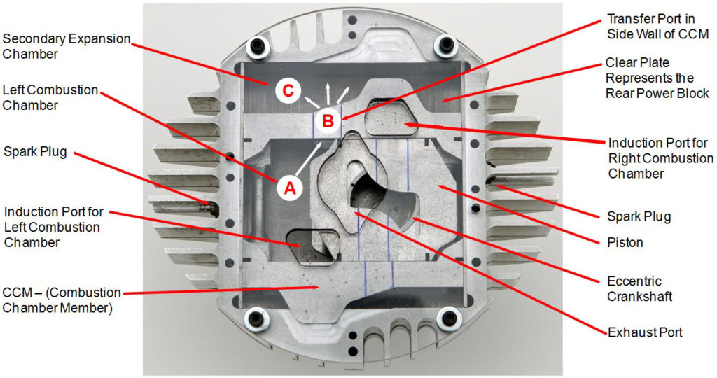
The image above is the view from the back of a 2.0 cubic inch FE-200 MCC engine. A clear rear power block was used to allow the porting and internal mechanism to be visible. The MCC engine uses an orbiting piston in a scotch yoke mechanism providing four, ported, variable volume chambers with only three moving parts. The three moving parts include the piston, Combustion Chamber Member (CCM) and eccentric crankshaft. The MCC engine is an inherent twin that fires once per revolution on each side of the engine. Only one piston is needed in this design to allow two separate combustion chambers to be ignited every 180° of the crankshaft’s rotation. This provides a very high torque engine. The piston is at bottom dead center and starting to move to the left in this view. The piston moves inside the combustion chamber member (CCM). The CCM is moving down in this view. Both the piston and CCM are moving simultaneously due to the piston being connected to an eccentric crankshaft. See MCC engine mechanism simulation below:
The volume made up by the left side of the piston and the inside of the CCM is the left combustion chamber shown at location A. At location B there is a transfer port in the side wall of the CCM to allow expansion to continue from the left combustion chamber into the secondary expansion chamber shown at location C. When the piston reaches bottom dead center (piston is fully to the right) the volumes A plus C equal 3.5 times the swept intake volume. This provides the MCC engine with a full expansion process that cannot be achieved in conventional engines. Full expansion significantly reduces the engine’s exhaust acoustic signature because the hot, high pressure gases from combustion are used to do more work in the engine before being exhausted. After the combustion gases reach atmospheric pressure then the exhaust gases are pushed out of the engine via transfer ports in the CCM and piston and a rotary port in the crankshaft.